Modeling Workflow
In the introduction, we looked at the structure of an omni-directional wheel and how it works. We examined how this wheel design allows the robot assembly to move in any direction. It does this without changing its orientation. It also achieves holonomic motion. Now, it’s time to translate that information into an actual virtual model. This model acts and behaves exactly like the real thing. This is where Simscape comes into the picture.
We will use the Multibody modeling tools in Simscape to build this model. We will hook up this model to control algorithms developed in Simulink and MATLAB. This model can also be used as a digital twin for the actual robot that I am building for my lab. I will talk about digital twins at length in another post.
In this post, we are going to build our robot model in a step-by-step fashion, as follows:
- Breakdown the model into a hierarchical structure
- Arrive at a flow-chart for building the parts
- Build steps:
We will attach the wheels to the robot chassis and model the interaction with the ground plane in the next blog entry.
If you would like to first go take a look at the basics of Multibody modeling in Simscape, follow the link to the documentation. You can find it in the getting started section at the bottom of the page..
Breakdown the model into a hierarchical structure
Let us start by breaking down the robot assembly into a hierarchical structure. This is how that structure looks conceptually.

Arrive at a flow-chart for building the parts
Starting out on a modeling project feels daunting when you look at the assembly as a whole. Still, once you have broken it down into smaller parts, it’s easy to see the repetitive elements. You need to model them only once. Also, as we model the smaller parts, the steps become more intuitive. When we assemble them into the next higher order part, the process becomes more straightforward. This is how the flowchart is actually going to look like once we get started.

Modeling the Passive wheel with axle
Before we start modeling the wheel, we are going to need some 3D models to represent its components. These components are the passive wheel and the wheel hub. Here is the STL file for the passive wheel used in this project:
Now that we have the 3D model for the wheel, let’s create a File Solid block in the Simscape model. First, set the unit type to Custom. Then, select the downloaded STL file. Set the unit type to Custom and select the downloaded STL file. You should see the wheel rendered in the preview window. Name the block as Wheel.

Make sure to check the “Convex Hull” option in the export section under Geometry. This is important. This allows the wheel to interact with other surfaces by providing a collision model. This collision model can be used by the physics engine.
You will notice that the wheel has a hole along it’s longer axis. We will align a cylindrical axle with this hole and use it to model the freely-rotating wheel motion. To achieve this, we will use a revolute joint and call it AxleToWheel Joint. We will use the default settings for this joint. Its rotation axis is already aligned with the Z-axis of the wheel. The reference frame for this setup is connected to an output port called R. The convex hull frame from the wheel is connected to an output port called CH.


Now, we can convert this assembly into a subsystem so that we can reuse it in our larger model.

Modeling the Wheel sub-assembly
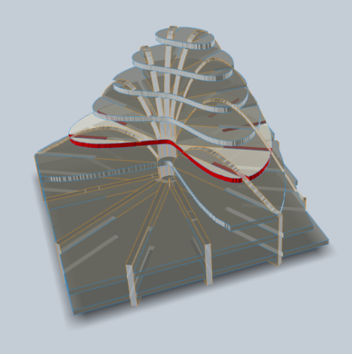
Now that we have a passive wheel part, we can use it to build our next part. This is the wheel sub-assembly consisting of a wheel hub and six passive wheels distributed along its circumference. The 3D part is shown below.
To start, let’s go ahead and add a File Solid block. Then, load the wheel hub STL file we downloaded earlier. Finally, call it Wheel_hub.

Let us start with one passive wheel and connect it to the hub with an appropriate transform. Once we have fine-tuned this connection, we can replicate it for the rest of the passive wheels. This is how the connection looks like:

The two transform blocks orient the passive wheel and hub with respect to each other and the reference frame. Here are the properties of each of the transform blocks:

The transform from the reference frame to the hub rotates the hub along the +Z-axis. This is done to align one of the ports to align horizontally. We will position the passive wheel to fit inside this port.

The transform from the reference frame to the passive wheel translates the wheel to its actual position. This translation ensures the passive wheel fits exactly inside the horizontally aligned port on the hub. This is how the assembly should look at this point:

The transform also aligns the +Z-axis for the passive wheel to the +X-axis of the hub. Similarly it aligns the +Y-axis of the passive wheel to the -Y-axis of the hub. This ensures that the passive wheel rotates freely inside the port it is aligned with in the correct direction.

Now, we can test the motion of this passive wheel and confirm its rotation. To do that, we must temporarily set the actuation property on the AxleToWheel_Joint to accept torque as an input. This adds an extra input port to the joint block called T.

Now, we can apply a constant torque to this joint and run the simulation. If everything is setup correct, we should see the passive wheel spin inside the hub port. To apply a constant value to this torque input port, we need to temporarily add a PS Constant block. This is how the connection should look like:

Now, we can run the simulation and we should see this:
Phew! Now that is some serious modeling work we just accomplished here. It is easy to see that the wheel on the opposite side has the same orientation. It is translated in the opposite direction. So, we can duplicate the blocks for the first wheel and just change its RefToWheelTransform block. We can now treat these two wheels as a pair. It is easy to see that the other two pairs are just rotated versions of this pair. By duplicating the pair and rotating it by 60 and 120 degrees, we can create the remaining wheels. By duplicating the wheels from the original one, we get the same axis alignment on all of them. This is how the final setup should look like:

Now, we have the wheel sub-assembly ready to go. This is how it should look like at this point:

Now, that we have the finished wheel sub-assembly, lets convert it into a reusable subsystem.

Finishing the wheel
In the introduction, we spoke about why we need two wheel sub-assemblies joined together. Now, lets get down to building the whole wheel with the sub-assembly we already created.

To finish the assembly, we start with joining two copies of the wheel sub-assembly with a Fixed or Weld joint. We apply a rotation transform to one of the sub-assemblies to rotate it by 30 degrees. The wheel is now finished structurally. We still need to add a way to rotate these wheels by applying external torque. We do this by adding a revolute joint and connecting it to the joined assembly. We enable the torque input in the actuation section and export the angular velocity in the sensing section. This allows us to connect a motor torque to the wheel, and sense its rotation.

And with this, the entire omni-directional wheel is now ready. We have not spoken about the blocks with dotted lines in the model at all. This is by design. We will talk about the convex hull and geometry connections when we get to the step where we want to simulate the motion of the entire robot on a ground plane. But, for now, sit back and sip on some coffee. You have earned it.
You can find the library model containing the finished wheel models in the GitHub repository link below.
https://github.com/artineering/omni-directional-robot
Getting Started with Simscape
There is very good documentation with examples to learn the basics of Multibody modeling with Simscape provided here: https://www.mathworks.com/help/sm/index.html?s_tid=CRUX_lftnav
3D Models
You can download the models from here: https://cults3d.com/en/3d-model/gadget/omni-wheels-for-robotics.